Understand common STL files errors and how to fix them
The ninth chapter is for anyone who has created or wants to produce an STL file for 3D printing and has difficulty producing the file.
This chapter will review the reasons why an STL file can be unprintable and possible solutions.
Preface
STL (acronym for: stereolithography or Standard Triangle Language) is the commonly used file for 3D printing. STL files use triangles (polygons) to represent the surfaces that make up the model. The triangles together form a network called MESH from which the model is composed. After the model works in the CAD software the file must be exported in STL format, this format will be transferred to the software that will deploy the model to the layers that the printer will create in the printing process.
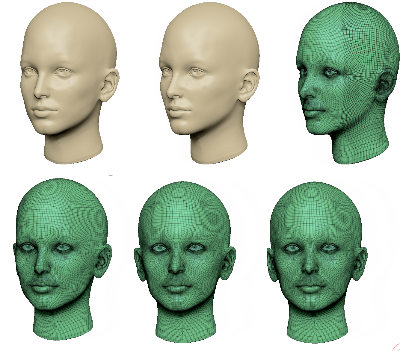
When designing a 3D model for printing, keep in mind that the computer model will become a physical model. While in the digital environment there are no physical laws and in fact it allows the creation of almost anything, the laws of physics will be applicable on the physical model and therefore not everything designed in computer software will be printable.
Therefore, there are STL files that can be viewed on a computer but are not printable.
This chapter will present the common errors that cause STL files to be unprintable and how to deal with it.
Unprintable STL file
Where each end of a polygon is connected to two additional polygons.
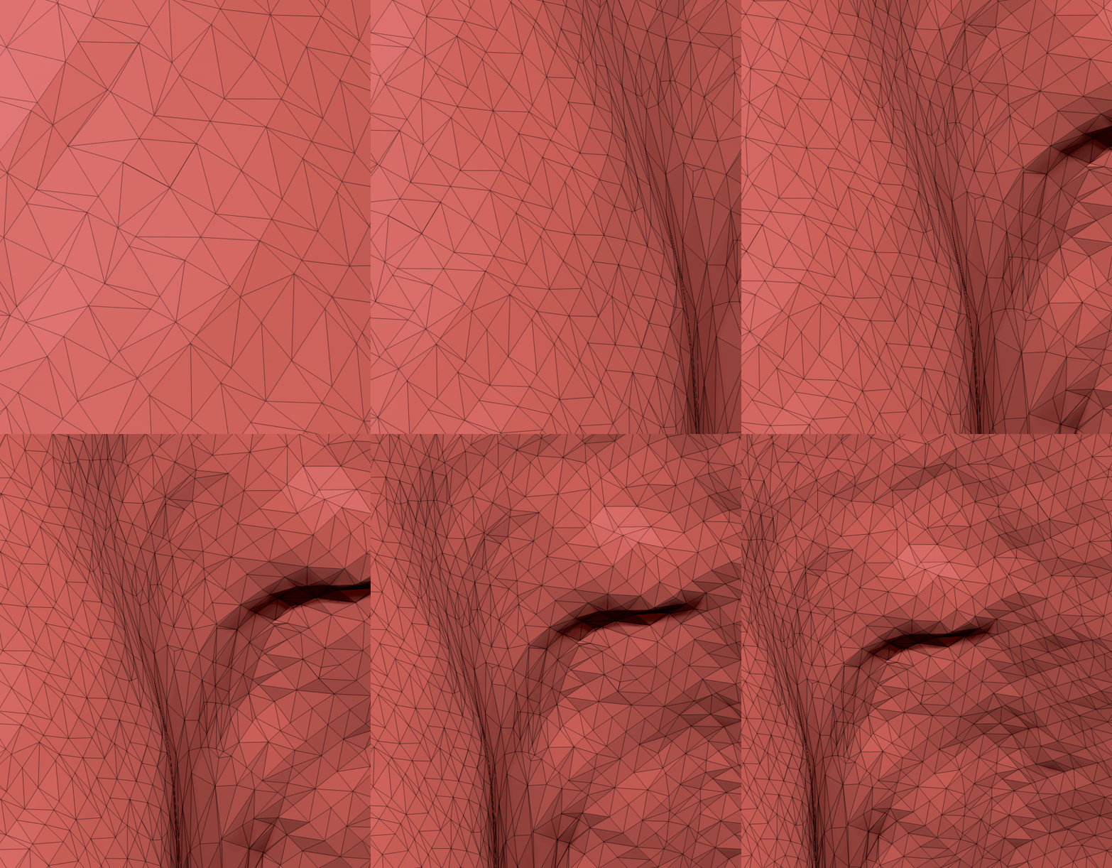
In some cases during the modeling process, the STL files are created damaged and unprintable. In this article we will review the causes of these defects and how they can be resolved.
Most of the problems in STL files are due to two main reasons:
- Problems in the distribution of the polygon network (polygons that collide with each other, detached polygons that float in space, lack of polygon in a certain area that is expressed as a hole)
- Structural defects in the model (holes in the model, number of elements in the model that collide, etc.)
The defects in the CAD software in which the models were created can be fixed (usually this option allows the problem to be solved from the root and the model produced according to the designer’s wishes)
In addition, there is a variety of software designed to repair and prepare print models ( Netfabb Meshmixer 3D Builder )
In addition, the quality of the STL files can be controlled by properly exporting the file.
For an article on Exports STL files
Boundary edges
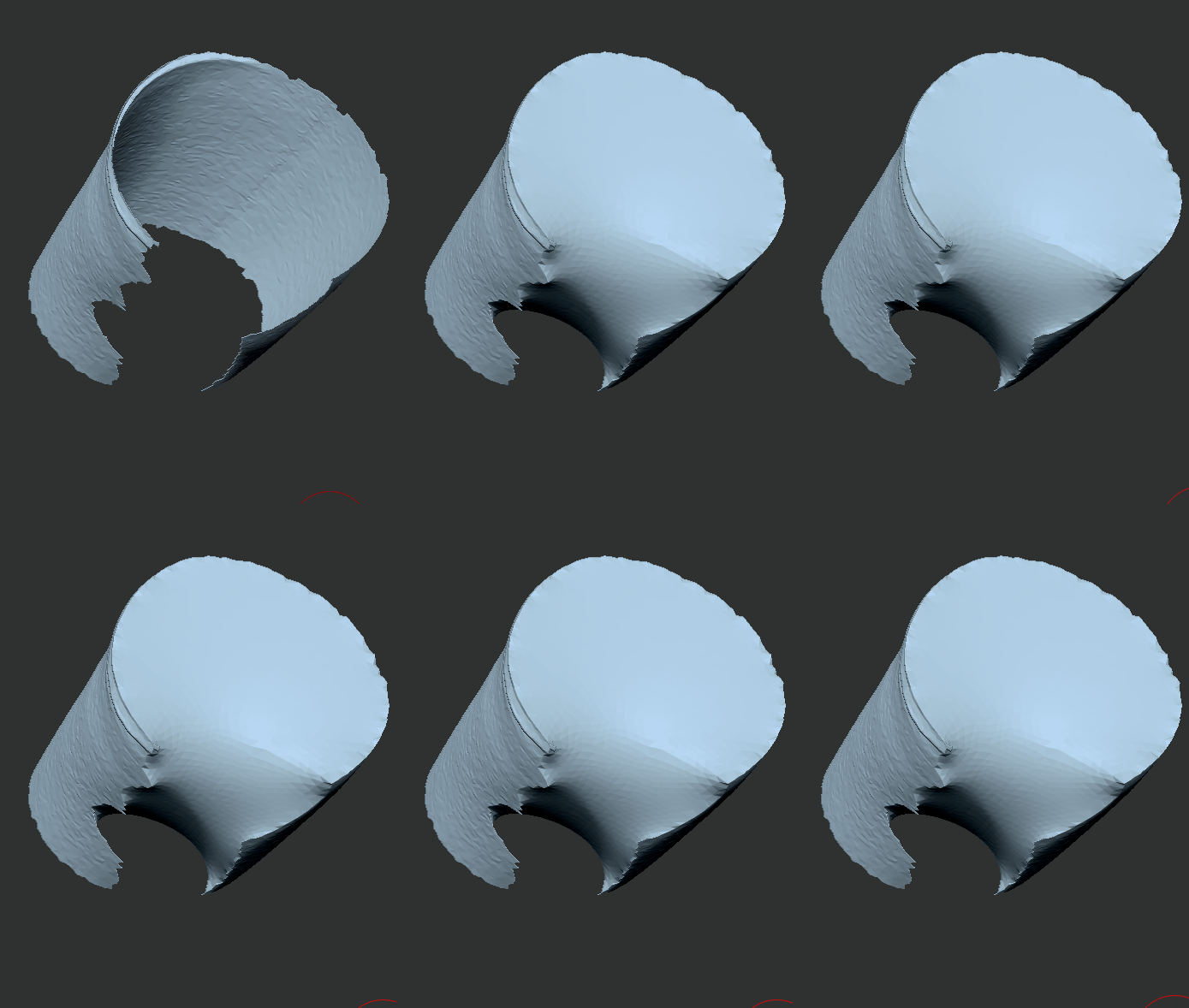
Boundary edges occur when some of the polygon vertices are not connected to two additional polygons. The holes form an open surface that is not printable.
solution:
Finding the hole area and closing it in the desired shape. When it comes to a relatively large hole or a hole with a complex closing geometry there are a variety of software that allow the closing of holes by creating bridges that direct the software to close the hole in the preferred manner.
In addition, a decision must be made on how to close the hole
Flat (FLAT) – The software will try to fill in the missing surface area with as flat a surface as possible. Recommended for engineering models with straight surfaces.
CURVATURE – The software will try to analyze the geometric structure of the area around the hole and track this geometry as the hole is completed. Recommended for amorphous models with curved terrain.
Colliding surfaces or polygons
Surfaces in a model usually collide when the STL file consists of several parts of the model between which there should be space but for some reason the files are located in a common area and collide with each other. This creates an internal space within the models and the cutting software does not know how to treat it. Sometimes a conflict occurs when several different STL files are imported into the cutting software and it places them in a way that causes a conflict between them.
solution:
When modeling, make sure that you maintain the desired spacing between the parts. Consolidate the separate model parts when they are located at the desired spacing for a single STL file.
Colliding polygons are the product of a faulty division of the polygon network.
Solution: Spot delete the colliding polygon (s). The eraser usually creates a hole and can be closed using the methods described.
Non-manifold edges
Imperfection in the distribution of the polygon network: when one end rib has more than two polygons attached to it.
Solution: Delete the excess polygon attached to the rib.
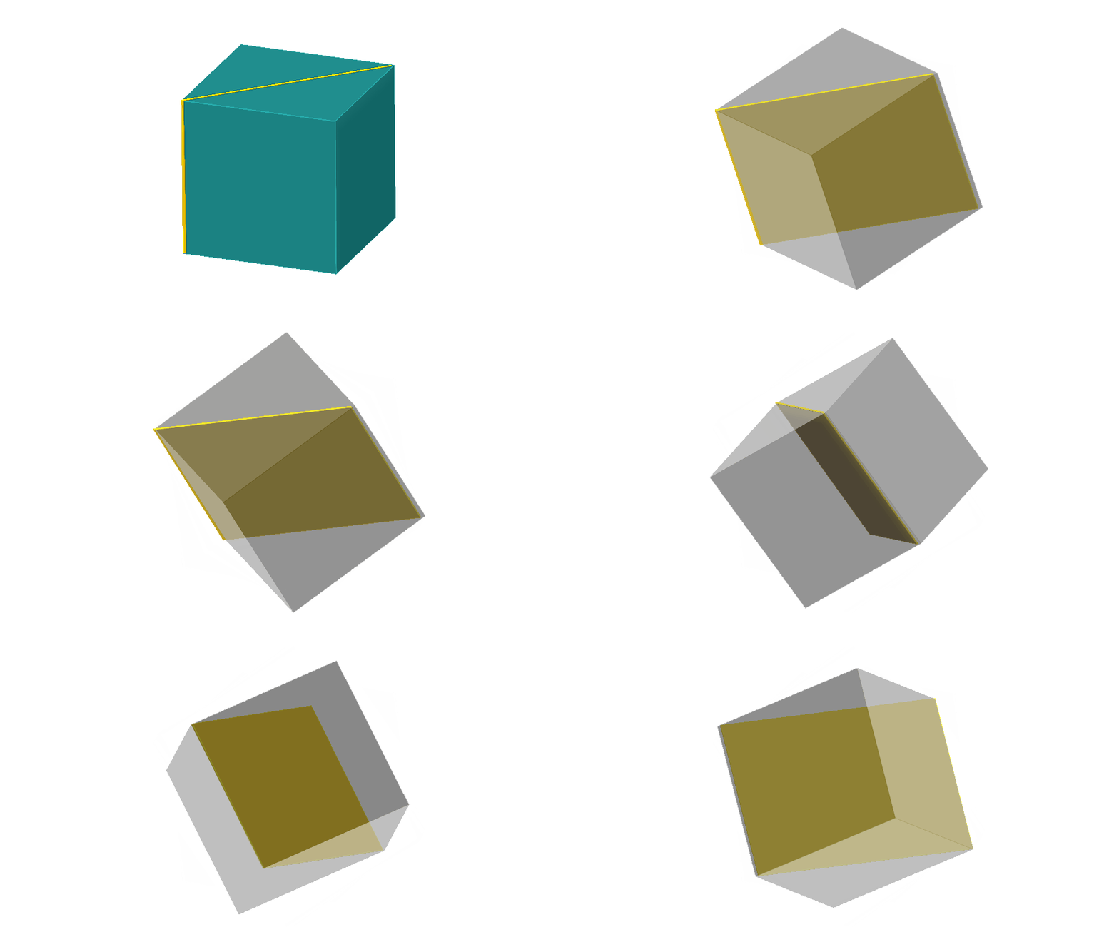
Defect in the model structure: This phenomenon can be noticed when two elements share one end rib: The reasons for the formation of such files: Misunderstanding that the connection between the two elements is not enough to hold them structurally. For technology. Or a modeling error when the goal was to produce two separate elements.
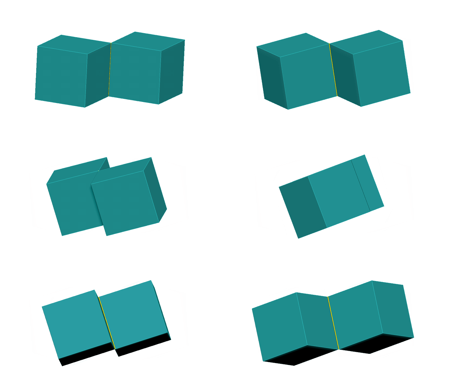
Solution: In case the model maker is interested in connecting the two elements-increasing the thickness of the connection between the two elements to the wall thickness recommended in the selected printing technology.
In case the model maker does not want to connect the two elements, the distance between the two elements must be increased. In addition it is recommended to save the two elements in one STL file when they are placed as needed.
- Chapter 1
What is 3D printing and what are its origins? - Chapter 2
The uses and purposes of 3D printing - Chapter 3
3D Printing Process - Chapter 4
How to choose 3D printing technology - Chapter 5
Overview of various 3D printing technologies - Chapter 6
General design guidelines for 3D printing - Chapter 7
CAD software classification - Chapter 8
3D Printing STL files: Introduction - Chapter 9
Understand common STL files errors and how to fix them - Chapter 10
SLS to MJF comparison - Chapter 11
Metal 3D Printing: Introduction - Chapter 12
How 3d metal printing change the world - Chapter 13
Metal 3D Printing Pros & Cons

